Highway Hydrogen Refuelling Systems


Hydraulically driven (partly closed loop)
• ASX-Technology (Automatic Seal Exchange)
• Max. discharge pressure up to 1.000 bar
• Max. compressor capacity above 1.200 Nm3/h
(100 kg/h) H2
• Average Energy Consumption ≈ 1,0 kWh/kg H2
Flow 15 – 200 kg H2/h Max pressure 1034bar
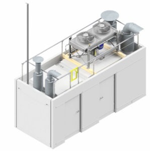
The heart of a hydrogen refuelling system is the MAX Compression System, which consists of a 2-stage hydraulically driven compressor. Developed for a maximum operating pressure of 1034 bar, the system can be operated with inlet pressures of 15 – 600 bar. A multifunctional containment fulfils the requirements for noise and fire protection and at the same time serves as a boundary for Ex zones on the hydrogen side. All necessary control elements, safety devices and auxiliary units for compressor operation are integrated in the MAX Compression System. Communication with adjacent modules takes place via Profinet, both for control and safety-related signals.

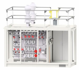
MAX Flow Tech System is the distribution station of the hydrogen refueling station, which ensures that the hydrogen is distributed to all system components as required. This module also contains the central control and intelligence of the entire HRS. MAX Flow Tech system is divided into a non-Ex area and an Ex area. This module contains separate chimneys to which all necessary internal relief connections are routed.

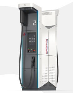
The MAX Dispenser 1.5 is the latest generation of hydrogen dispensers from Maximator Hydrogen. It sets new standards in terms of user experience and safety and combines the knowledge gained from over 20 years of experience in high-pressure technology and over 100,000 hydrogen refuelling operations in a new design. The dispenser has been designed in such a way that all components required for refuelling (refuelling valve, flow meter, ramp regulator, etc.) are ergonomically arranged. The design is appealing to the customer, the customer journey is user-friendly and enables easy maintenance on site.

The MAX ReCab provides the connection to the target storage (trailer). After manually coupling the target storage, the further steps take place fully automatically. After coupling, the connection hose is rinsed several times for safety reasons.
The MAX ReCab consists of the following core components:
– pneumatically operated high-pressure valves for flushing and filling the trailer
– Safety valve
– Mass flow sensor for the exact determination of the filling quantity
– Connection for one trailer
– filling pressure of the trailer: customized
– Control Panel for operation (touch panel optional)
With the fully automatic version, the trailer is coupled and uncoupled manually. The filling process must then be started once at the control panel. The hose is then rinsed, and the trailer is filled fully automatically according to a predefined ramp. During the filling process, the safety functions temperature (max. 65°C, depending on trailer specification) and max. filling pressure (depending on trailer) are monitored. The filling process is carried out in accordance with the (storage system) manufacturer’s instructions.


MAX Storage is divided into medium pressure (MP) and high pressure (HP) and describes stationary type I or optionally type II hydrogen storage tanks.
The number and configuration of the entire MAX Storage can be adapted to customer requirements.
The MAX Storage is a high-pressure hydrogen storage system including valve block, which is installed as a separate module and stores the hydrogen within the MAX Compression System.
MAX Storage HP consists of 15 x 5 L high-pressure tanks in rack type II.

The MAX Supply Storage forms the electrolysis interface module, which
essentially consists of an 850 l buffer type IV. The system can connect up to 2 MAX Compression Systems and is grouped together in a container equipped with all necessary installations.
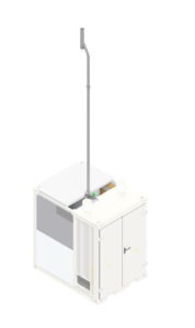
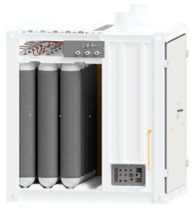
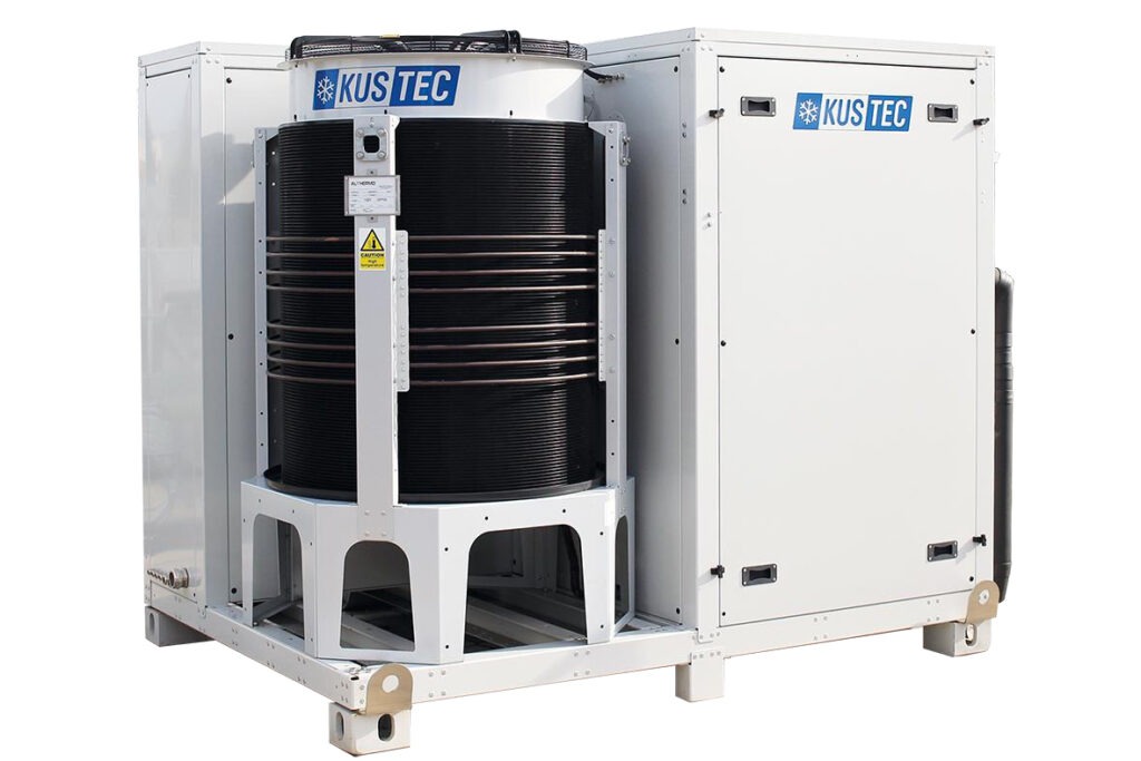
MAX Chill is the refrigeration system that preconditions the hydrogen for vehicle refuelling.
The cooling system consists of up to two refrigerant circuits: A primary circuit with R449A and a secondary circuit with R744 (CO2). The secondary circuit is responsible for cooling the hydrogen through the heat exchanger in the dispenser. In the CO2 variants, only CO2 is used in both circuits.
This system is designed to cool the plate heat exchanger in the MAX Dispenser online (as soon as a vehicle refill is requested). The stored hydrogen from the storage flows through the heat exchanger and is cooled to provide refuelling of the appropriate temperature class. All components are housed in a separate enclosure for outdoor installation.

Our customers can choose from three different filling ramps. In addition to the flexible MC method and a fixed, tabular refuelling ramp, we offer our own in-house development – the Multi Ramp – for uncooled vehicle refuellings in the commercial vehicle sector with the Multi Ramp. This enables higher flexibility for all important processes and thus increases the availability of your system.
Advantages Multi Ramp | 350 bar:
- Dynamic refueling protocol
- Faster and optimized interaction from the H2 delivery via the refuelling station to the commercial vehicle
- Consideration of storage utilization, bank switching and the Joule-Thomson effect
- Higher system availability
- Cost reduction for OPEX and CAPEX
- Less space required for the entire refuelling system

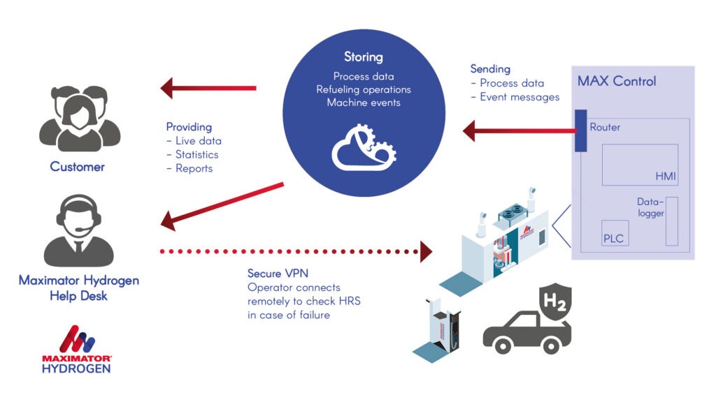
The Maximator Hydrogen Cloud allows refuelling station operators to plan service times themselves, access system documents, query the current status of the HRS and also control the refuelling station remotely.
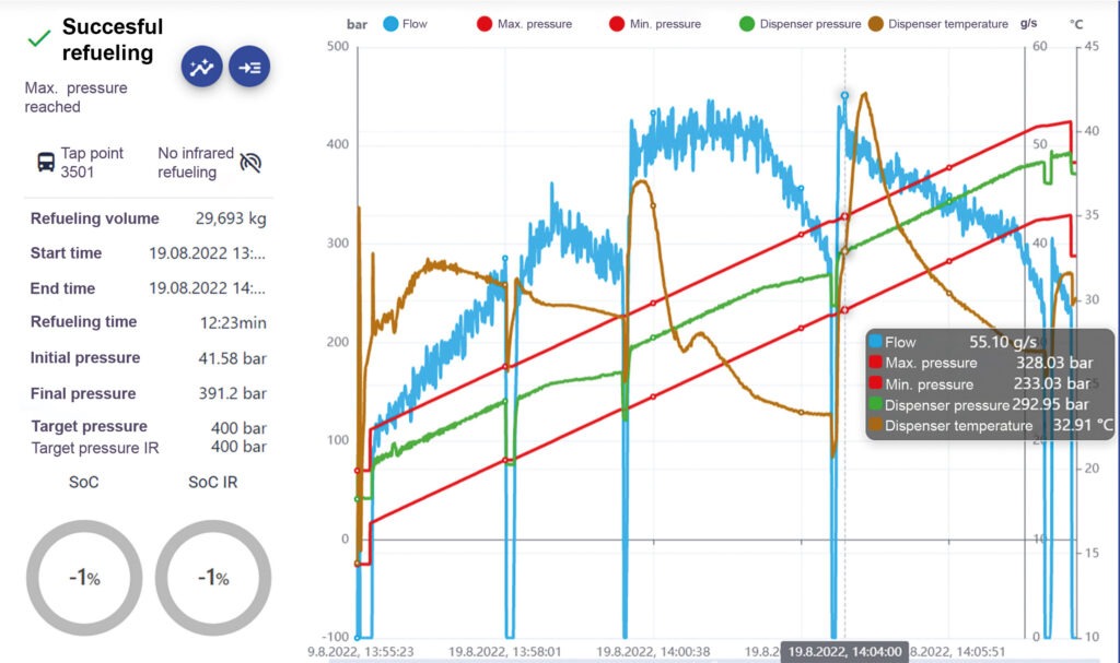
Our hydrogen refuelling stations contain a digital platform that enables extensive analyses. A dashboard provides customers with a 24/7 overview of the functions of all their refuelling stations and records, for example, refuelling operations, hydrogen deliveries as well as errors and warnings. Performance and possible faults are visible at a glance and can be remedied in real time without delay
The Maximator Hydrogen Cloud offers real-time reports with a graphical representation of the status of the hydrogen refuelling systems (HRS); for example, how often and when refueling takes place, how many kilograms of hydrogen are needed, how much turnover is generated with the HRS
or when the next service is due.
The dashboard is visible as a panel PC in the MAX Control unit. This is where all the collected data is brought together. The dashboard can be freely configured to meet the varying
needs of every customer.
Hydrogen Refuelling Systems - Application Example
Max Compression System Video 1
Max Compression System - Further Modules Video
If you are interested in a quotation for one of our Highway Hydrogen Refuelling Systems, please click on the button below, or get in contact with our office
Tel 01606 636000 or email sales@maximator.co.ukway